

 Home /
 How to Read Pneumatic Valve Diagrams Symbols and Guide
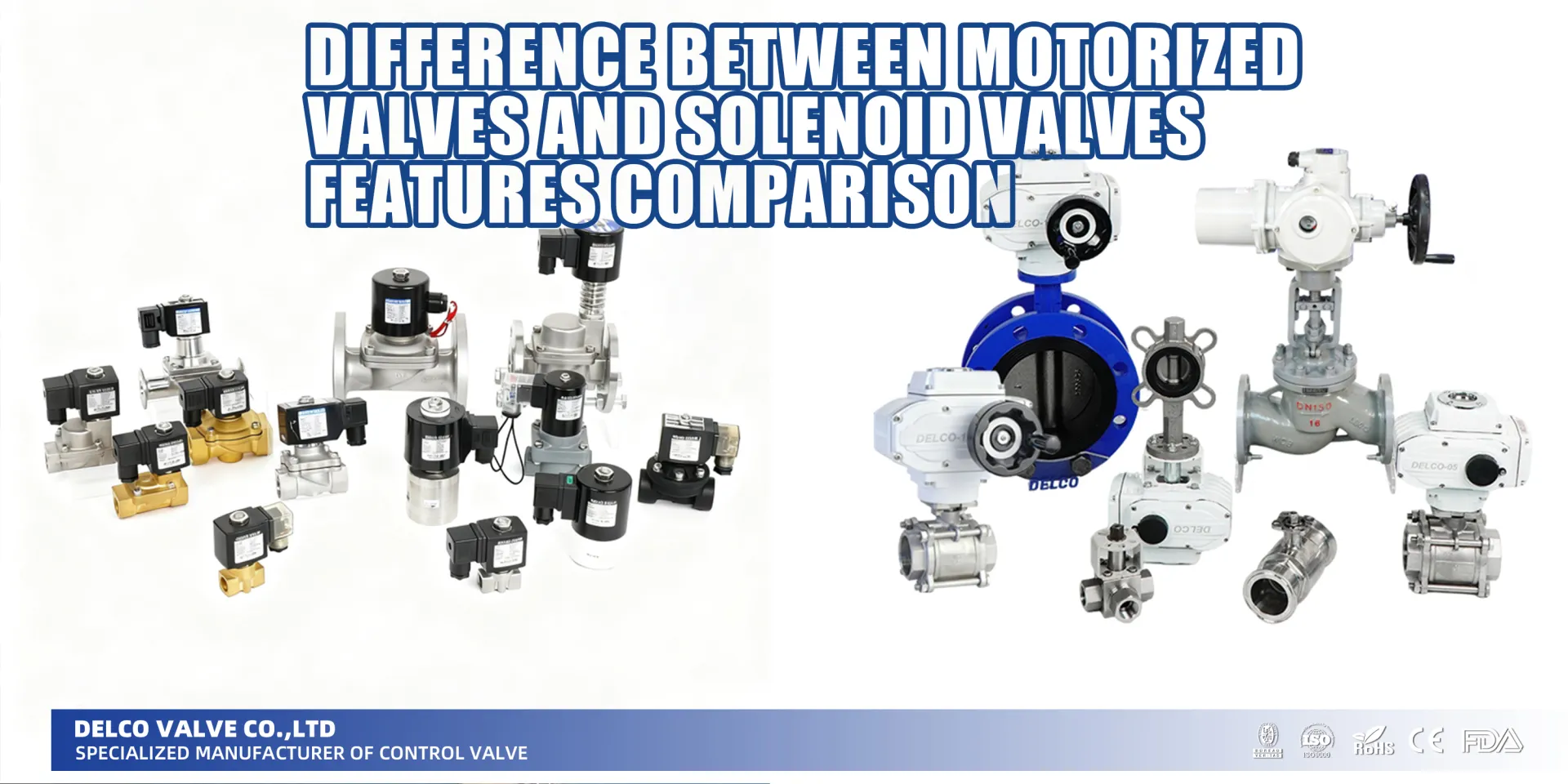
Difference Between Motorized Valves and Solenoid Valves Features Comparison
Nov 29, 2025
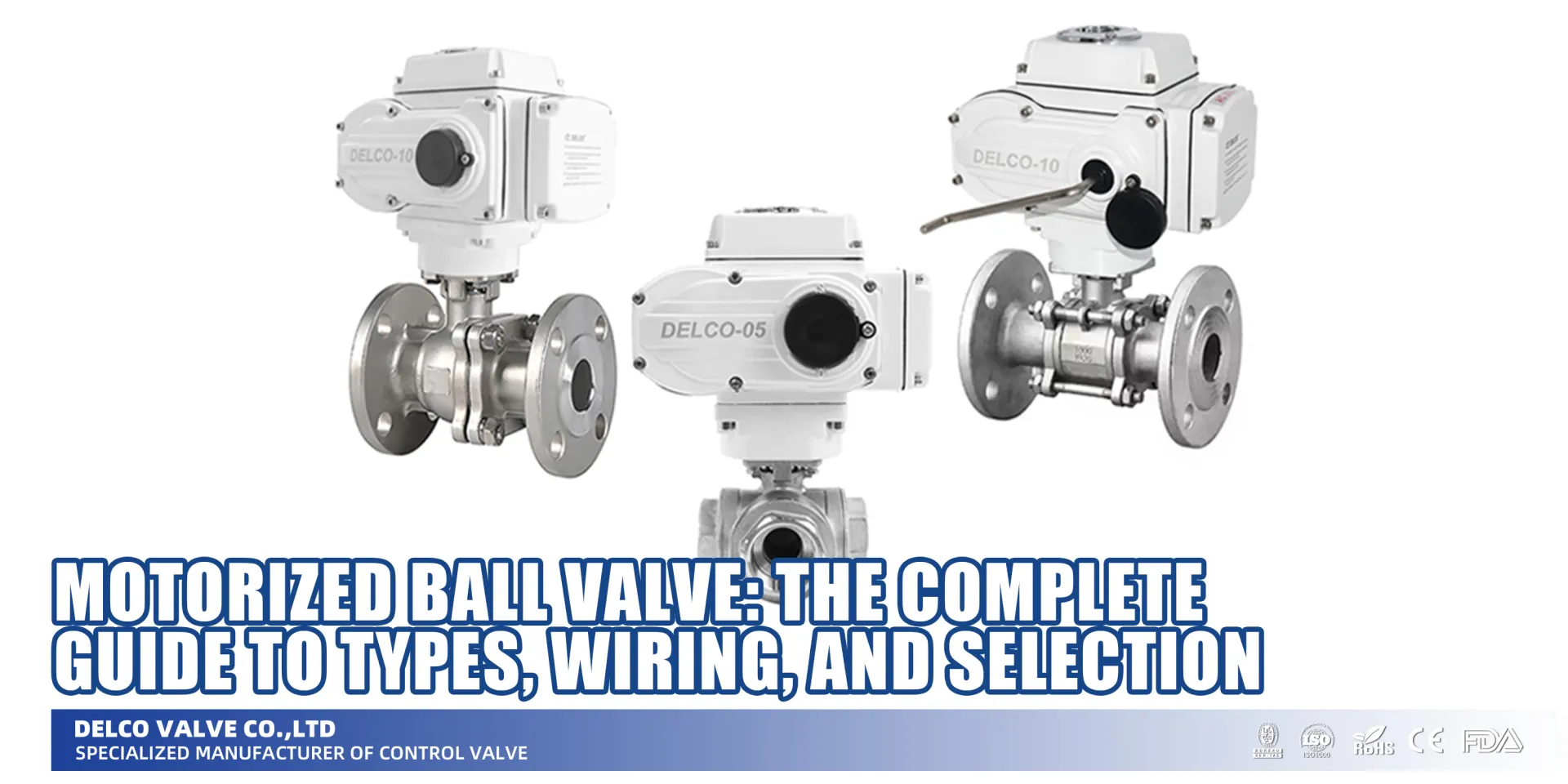
Motorized Ball Valve: The Complete Guide to Types, Wiring, and Selection
Dec 29, 2025
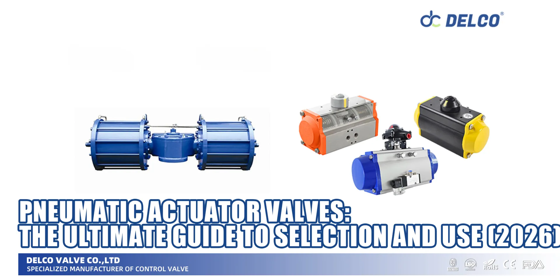
Pneumatic Actuator Valves: The Ultimate Guide to Selection and Use (2026)
Jan 14, 2026
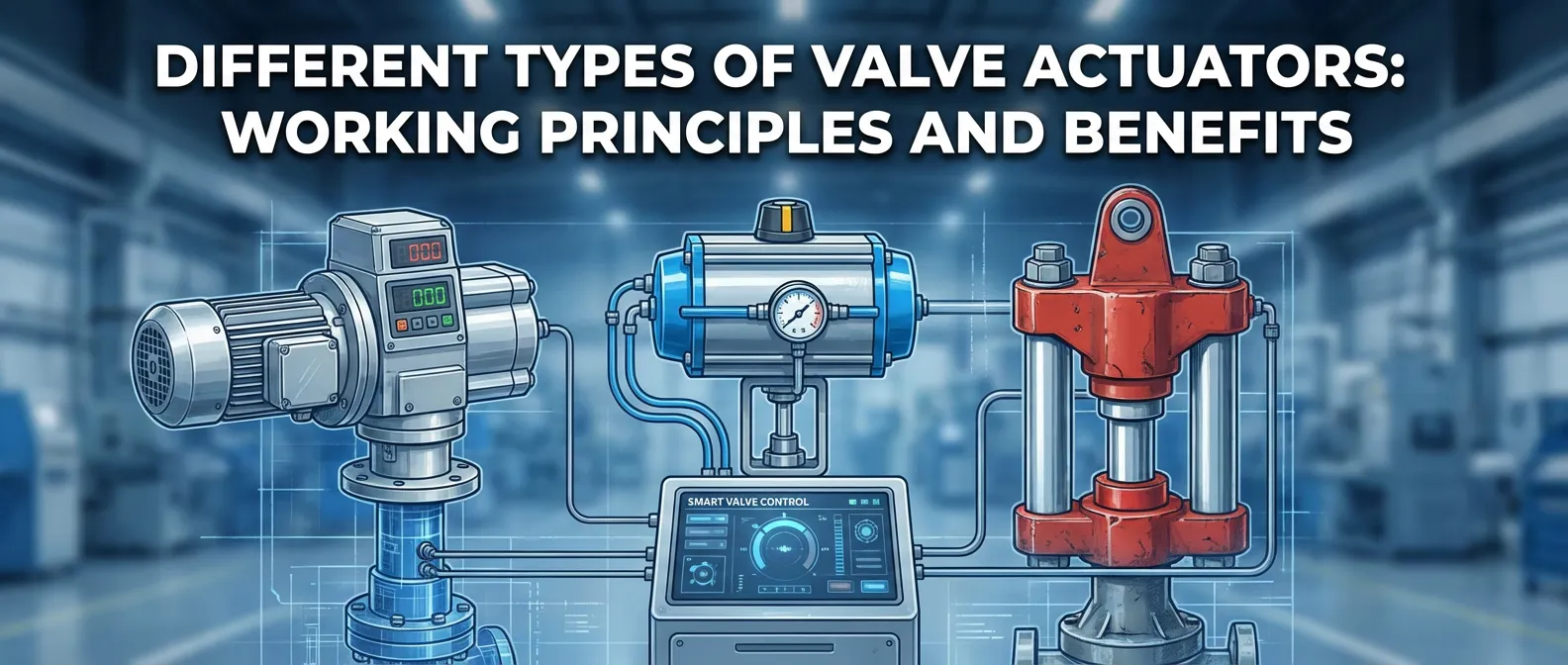
Different Types of Valve Actuators Working Principles and Benefits
Nov 29, 2025
Are you staring at a confusing web of lines and squares, struggling to figure out exactly how to read pneumatic valve diagrams?
You might already know that understanding these schematics is absolutely critical for keeping industrial systems running smoothly…
But what do all those little boxes, arrows, and port numbers actually mean?
Well, you’re in for a treat because I’ve put together a complete, step-by-step guide.
As someone who has spent years in industrial maintenance, I know that mastering pneumatic schematic symbols is the fastest way to upgrade your troubleshooting skills. I’m going to give you advice that skips the overly dense engineering jargon and focuses on what actually works on the shop floor.
In this post, you’re going to learn exactly how to decode the “box” logic, map out internal flow paths, and identify different actuation methods—from simple push buttons to complex solenoid triggers.
Whether you’re trying to figure out the difference between a 3/2-way and a 5/2-way valve, or you just want a reliable system to read a complete air circuit in under 5 minutes, this guide is for you.
Let’s dive right in.
Introduction to Pneumatic Schematic Symbols and Their Importance
Pneumatic symbols are the universal language of fluid power engineering. Whether you are designing a complex automation system or troubleshooting a malfunctioning machine on the factory floor, understanding a schematic diagram is an absolute necessity.
These graphical representations eliminate language barriers, providing a clear, standardized map of how air flows through a system. Relying on international standards like ISO 1219, these diagrams ensure that engineers and technicians worldwide can interpret the exact function of every component without ambiguity.
Why Mastering Pneumatic Symbols is Critical:
- Rapid Troubleshooting: Instantly locate faults within a pneumatic circuit by tracing the intended airflow path.
- Universal Communication: Seamlessly share designs across global teams using standardized pneumatic symbols.
- Operational Safety: Correctly identifying directional control valve functions prevents catastrophic system failures and ensures safe maintenance protocols.
- Efficient System Design: Translate complex mechanical requirements into streamlined, easy-to-read visual logic.
Knowing how to read these symbols transforms a confusing maze of lines and boxes into a precise, logical blueprint, empowering you to build, maintain, and repair pneumatic systems with complete confidence.
Understanding the “Box” Logic: Positions and Ports
When I first learned how to read pneumatic valve diagrams, the biggest hurdle was understanding the basic geometry. In any schematic diagram, the boxes are the foundation. They define exactly how a directional control valve operates and routes air. Let’s break down this visual logic.
What do the Squares Represent? (Valve Positions)
In pneumatic symbols, every square represents a distinct switching position the valve can take. The number of adjacent squares tells you the total number of positions available.
- Two Squares: The valve has two positions. This is the standard setup for simple on/off functions, like what you find in a basic 3/2-way valve.
- Three Squares: The valve has three positions. Often, the center square represents the resting or neutral state of the valve.
- The Active Box: The specific box that has the external lines connected directly to it represents the current, unactuated state of the valve.
Understanding Internal Flow Paths (Arrows and Lines)
Once you understand the positions, you need to look inside the squares to track the airflow path.
- Directional Arrows: These straight or angled arrows indicate the exact direction the compressed air is moving through the valve.
- T-Symbols (Tees): A line that ends in a flat horizontal line (forming a “T”) means the port is completely blocked. No air can pass through this path.
- Solid Lines: These lines inside the box show how the different internal valve ports connect to each other in that specific position.
Identifying Port Numbers and Letters (ISO 1219 vs. ANSI)
Accurate port identification is what makes or breaks a working pneumatic circuit. Depending on the equipment’s origin, you will usually encounter two main standards for labeling ports: the international ISO 1219 standard (using numbers) and the older ANSI standard (using letters).
Here is a quick breakdown to help you map them out:
| Port Function | ISO 1219 Standard | ANSI Standard |
|---|---|---|
| Pressure / Supply Inlet | 1 | P |
| Working / Output Ports | 2, 4 | A, B |
| Exhaust Port | 3, 5 | R, S |
I always rely on the ISO 1219 standard, as it is the globally recognized format you will see on modern equipment. Memorizing these labels ensures you connect your main supply lines and exhaust ports exactly where they belong without any guesswork.
Common Pneumatic Valve Symbols Explained
Once you grasp the basic boxes and ports, reading pneumatic valve diagrams becomes straightforward. Let’s break down the most common directional control valve symbols you will spot on any standard schematic diagram.
2/2-Way Valves: The Basics of On/Off Control
The 2/2-way valve is the simplest directional control valve in our lineup. It features two ports and two positions.
- Core Function: Acts as a basic shut-off valve to start or stop the airflow path.
- Common States: Can be configured as Normally Closed (NC) or Normally Open (NO).
- Ideal Application: Perfect for isolating sections of a pneumatic circuit or running simple air blow-off tasks.
3/2-Way Valves: Controlling Single-Acting Cylinders
When we need to operate a single-acting cylinder, the 3/2-way valve is the standard choice. It uses three valve ports (supply, output, and an exhaust port) across two positions.
- How it works: It directs air to push the cylinder out, then switches to vent the air through the exhaust port, allowing a spring return to pull the cylinder back.
- Versatility: Available in both Normally Closed (NC) and Normally Open (NO) setups.
- Usage: Frequently used as a pilot operated trigger or to power single-acting actuators.
5/2-Way and 5/3-Way Valves: Workhorses for Double-Acting Actuators
For demanding automated tasks, we rely on 5/2-way and 5/3-way valves to drive double-acting cylinders. These handle more complex routing using five distinct valve ports.
| Valve Type | Positions | Primary Function |
|---|---|---|
| 5/2-Way Valve | 2 | Alternates airflow between two outputs to fully extend and retract a cylinder. |
| 5/3-Way Valve | 3 | Features a center position. Used to hold a cylinder mid-stroke or safely exhaust all system air. |
Actuation Methods
When figuring out how to read pneumatic valve diagrams, I always check the far left and right ends of the valve “box.” These outer symbols represent the actuation methods—exactly what triggers the directional control valve to shift and change the airflow path.
Mechanical Actuator & Manual Control
These triggers require direct physical force to move the valve spool.
- Manual Control: Driven by human action. You will see simple symbols indicating push buttons, hand levers, or foot pedals.
- Mechanical Actuator: Triggered by moving machine parts. Look for a circle symbol indicating a roller, or a plunger lever that acts as a limit switch when a cylinder hits it.
Solenoid Valve & Pilot Operated
Automated systems rely on electrical or pneumatic signals to control the valve remotely.
- Solenoid Valve: Uses an electrical coil to shift the valve. The symbol is a small box with a diagonal line inside. This is the industry standard for computer or PLC-controlled circuits.
- Pilot Operated: Uses secondary air pressure to trigger the shift. You will spot this represented as a dashed line pointing directly into the side of the valve block. It is highly reliable for heavy-duty or all-pneumatic systems.
Spring Return vs. Detent Logic
Once the actuation trigger is removed, the valve needs a mechanism to determine its next state.
- Spring Return: Represented by a jagged, zigzag line. The moment you cut the power or release the button, the spring automatically forces the valve back to its normal resting position.
- Detent: Represented by a notch or ‘V’ symbol. A detent acts like a mechanical memory lock. It keeps the valve held exactly in its last shifted position until an opposing signal actively pushes it back.
Step-by-Step Guide: How to Decode a Pneumatic Diagram in 5 Minutes
Learning how to read pneumatic valve diagrams doesn’t have to be a complicated, drawn-out process. When we analyze a schematic diagram for a new fluid control project, we follow a strict, repeatable method to quickly understand the system’s requirements. Whether you are looking at a simple water treatment skid or a complex chemical process control system, you can decode the core logic in just a few minutes.
Here is our straightforward, five-step process to break down any pneumatic circuit:
- Step 1: Count the Boxes (Positions)
Look directly at the main directional control valve symbol. The number of adjacent squares tells you the number of positions the valve has. Two squares mean a two-position valve (typically open/closed), while three squares indicate a three-position setup. - Step 2: Count the Ports (Ways)
Focus on the “default” box, which is usually the right-hand square for a spring return valve. Count every point where a line touches the outside of that specific box. This port identification quickly tells you if you are dealing with a 3/2-way valve or a 5/2-way valve. - Step 3: Trace the Airflow Path
Look at the arrows inside the active box. These arrows map the exact airflow path from the supply line to the working ports, and eventually out through the exhaust port. This shows you exactly how the compressed air will move when the valve shifts. - Step 4: Identify the Actuation Methods
Check the symbols attached to the far left and right sides of the boxes. This is where you determine how the valve is triggered. You might see a zig-zag line for a spring return, or a diagonal line in a box for a solenoid valve. This step is critical for determining if you need Single Acting or Double Acting pneumatic actuators, like our AT Series (Rack and Pinion) or AW Series (Scotch Yoke). - Step 5: Extract the Technical Specs
Once you understand the logic, translate the diagram into real-world procurement specs. The schematic dictates the pressure ratings, actuation types, and control signals (like 4-20mA loops) required.
By following these five steps, you move seamlessly from a theoretical drawing to actionable specifications. Understanding the diagram ensures you source the correct industrial-grade components, whether your project requires standard configurations or highly customized, ATEX and SIL-compliant pneumatic valves.
Real-World Example: Analyzing a Complete Air Circuit
Let’s put the theory into practice. When I teach people how to read pneumatic valve diagrams, I always start by breaking down a complete pneumatic circuit from the bottom up.
Here is a quick, step-by-step breakdown of a standard circuit used to control a double-acting cylinder:
- The Air Supply: At the very bottom of the schematic diagram, you will spot a triangle symbol pointing upward. This represents our main compressed air source.
- The Input Trigger: Next up is a manual push-button, usually represented as a 3/2-way valve. It acts as our trigger. When pressed, it opens the airflow path and sends an air signal down the line.
- The Main Controller: That air signal travels to a pilot operated directional control valve—typically a 5/2-way valve. The incoming pilot air physically shifts the active position block inside this main valve.
- The Action: Once shifted, the 5/2-way valve routes high-pressure air directly into the rear port of the cylinder, forcing the rod to extend.
- The Exhaust: As the cylinder pushes forward, the trapped air on the opposite side needs somewhere to go. It flows back through the 5/2-way valve and is safely vented to the atmosphere through a dedicated exhaust port.
By following these logic blocks step-by-step, you can easily trace the air through the entire system and troubleshoot exactly where a process might be failing.
Troubleshooting: How to Read Worn or Non-Standard Symbols
In harsh industrial environments, a schematic diagram taped to a control panel rarely stays pristine. We frequently encounter worn out, faded, or completely non-standard pneumatic symbols on older equipment. When a diagram does not strictly follow modern ISO 1219 standards, you have to reverse-engineer the valve logic using the physical hardware.
Here is how we recommend troubleshooting unreadable or legacy diagrams:
- Count the Physical Valve Ports: If the drawing is faded, look at the actual valve body. Count the main connections. Three ports usually mean a 3/2-way valve, while five ports indicate a 5/2-way or 5/3-way directional control valve.
- Check the Stamped Port Identification: Even if the paper schematic is ruined, the metal valve body often has numbers or letters stamped near the threads. Look for 1, 2, 3, 4, 5 (ISO) or P, A, B, R, S to map out the intended airflow path.
- Identify the Actuation Methods Visually: Cannot read the trigger symbol on the paper? Inspect the hardware. A visible electrical coil means it is a solenoid valve, an attached small air line to the end cap indicates it is pilot operated, and an extended housing on one side usually confirms a spring return mechanism.
- Locate the Exhaust Port: Non-standard drawings sometimes omit exhaust lines entirely. Find the physical exhaust port on the valve (often fitted with a bronze or plastic muffler) to understand exactly where the system vents pressure.
When legacy diagrams fail, mapping the physical connections ensures you specify the exact replacement needed. If you are struggling to decode an old schematic for a critical pipeline, our engineering team routinely helps clients match existing setups with our modern, ISO-certified pneumatic actuators and automated valves to keep operations running safely.
Frequently Asked Questions (FAQ) about Pneumatic Valve Diagrams
What is the difference between a 3/2-way and a 5/2-way valve symbol?
The main difference lies in the number of valve ports and their application in your system.
- 3/2-way valve: Features 3 ports and 2 positions. We primarily use these to control single-acting cylinders where only one working line is needed.
- 5/2-way valve: Features 5 ports and 2 positions. This directional control valve is the industry standard for double-acting actuators because it provides independent exhaust paths for each side of the cylinder.
What do the numbers 1, 2, 3, 4, and 5 represent on pneumatic valve ports?
Standard port identification relies on a universally recognized numbering system to map out your connections:
- 1: Main air supply (pressure inlet).
- 2 and 4: Working ports (lines connecting directly to your actuator).
- 3 and 5: Exhaust port connections (venting used air out of the system).
How can I identify a Normally Closed (NC) vs. a Normally Open (NO) valve diagram?
To tell the difference, look at the resting state box in the schematic diagram—this is usually the box positioned next to the spring return symbol.
- Normally closed (NC): The airflow path from port 1 is visually blocked by a “T” symbol. No air passes until the valve triggers.
- Normally open (NO): Port 1 connects directly to a working port (like port 2) with a straight arrow. Air flows freely by default.
What does a dashed line represent in a pneumatic schematic?
In any standard pneumatic circuit, a dashed line indicates a pilot air signal. This tells us the component is pilot operated. Instead of shifting via a direct mechanical actuator or internal solenoid valve coil, the main valve spool shifts when a smaller, secondary air signal hits the pilot port.
What is the difference between ISO 1219 and ANSI pneumatic symbols?
Both systems standardize pneumatic symbols, but they label the ports quite differently.
- ISO 1219: Uses a numerical system (1, 2, 3, 4, 5). We use this as the modern global standard.
- ANSI: Uses a lettering system (P for Pressure, A/B for working lines, EA/EB for exhausts). You will mostly see this on older North American equipment.
How do I read the flow direction in a multi-position valve symbol?
You determine the flow by tracking the arrows inside the active “box” of the symbol.
- Identify the resting block.
- Apply your actuation methods (mentally shifting the box over to the active state).
- Follow the solid arrows inside that newly activated box—they clearly show the exact path the pressurized air will travel between ports.
Share on Social:
Contact Us
In This Article
Difference Between Motorized Valves and Solenoid Valves Features Comparison
Nov 29, 2025
Motorized Ball Valve: The Complete Guide to Types, Wiring, and Selection
Dec 29, 2025
Pneumatic Actuator Valves: The Ultimate Guide to Selection and Use (2026)
Jan 14, 2026
Different Types of Valve Actuators Working Principles and Benefits
Nov 29, 2025